Flight controller · In design
NAVIX X427 Mini
The X427, made small.
An STM32F427 at 180 MHz, an IMU, a barometer, CAN and eight PWM outputs, on a 36 x 36 mm board with the standard 30.5 mm mounting pattern.
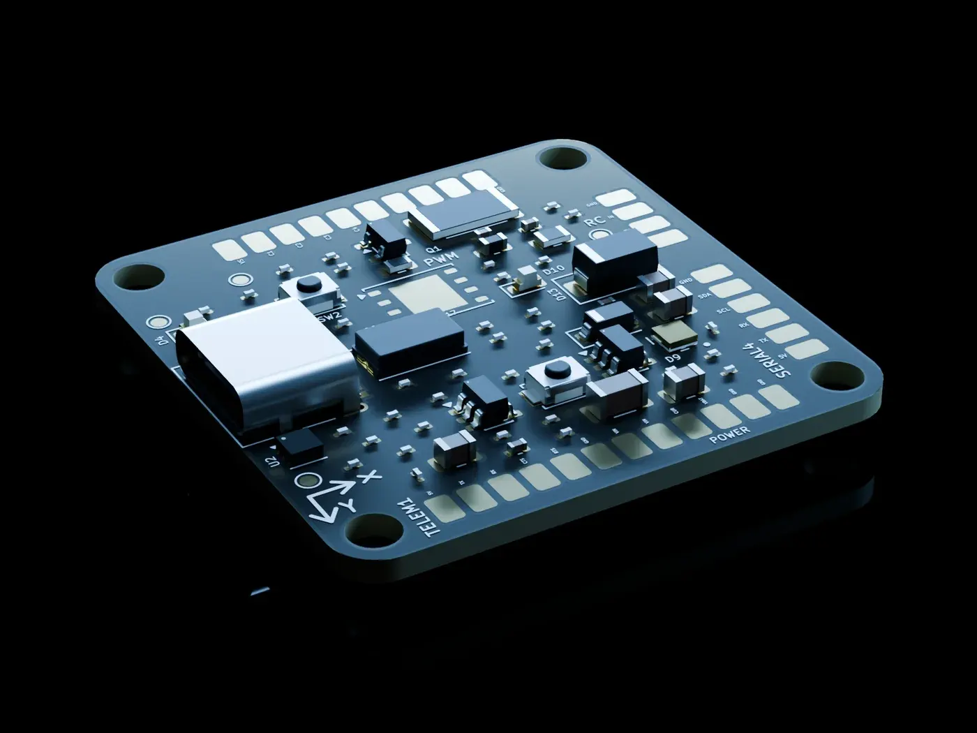
The same processor, on a board a quarter the size.
The X427 Mini is a four-layer flight controller built around the same STM32F427 as the X427. Compared with the X427 it has one IMU instead of up to three, eight PWM outputs instead of fourteen, and onboard flash instead of a microSD slot. It is in design: this page describes the schematic and board layout, not a built board.
- 180MHz
- Cortex-M4F
- 8PWM
- motor outputs
- 16MB
- onboard flash
- 36 x 36mm
- 4-layer board
Overview
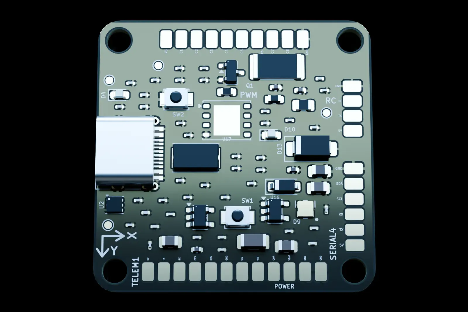
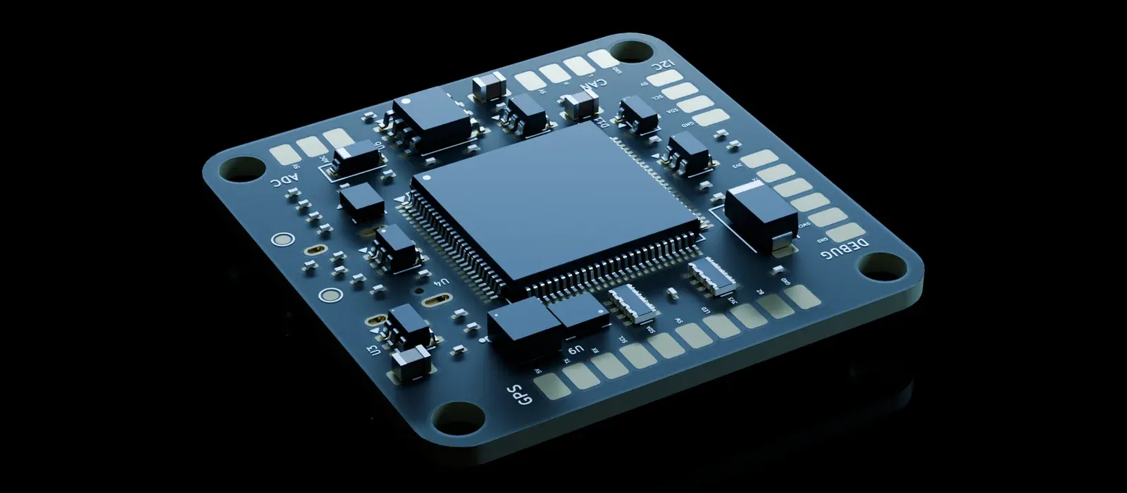
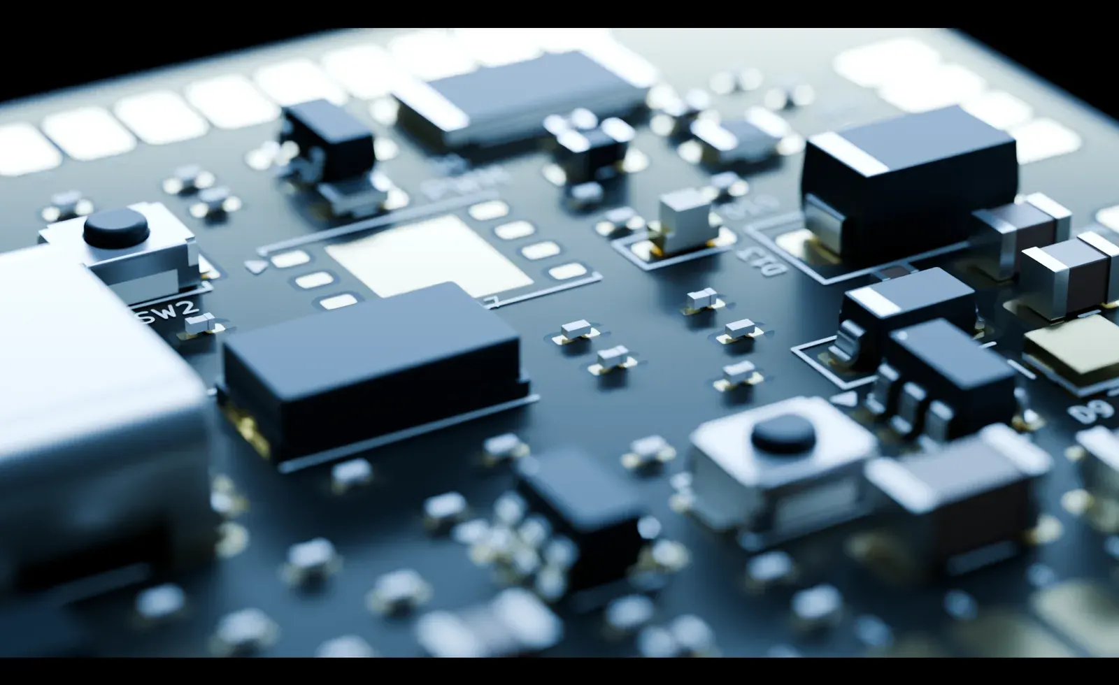
The board, from above and below.
The ports are solder pads along the edges. USB-C, the BOOT and RESET buttons and most of the small parts are on the top; the STM32F427 is on the bottom.
These are renders of the design, not photographs of a built board.
What it does
Six things worth knowing.
The same core as the X427.
An STM32F427VGT6 runs a Cortex-M4F at 180 MHz with 1 MB of flash and 256 KB of SRAM, from an 8 MHz crystal. 58 of its 82 I/O pins are in use.
- 180 MHz
- 1 MB flash
- 192 + 64 KB SRAM
- 58 of 82 I/O used
An IMU, a barometer and flash for logs.
An LSM6DSOX IMU on SPI1 and a BMP585 barometer on I2C. A 16 MB flash chip on its own SPI bus takes the place of the X427's microSD slot. There is no compass on the board: use the one in your GPS module.
- LSM6DSOX
- BMP585
- 16 MB flash
- No onboard compass
Two power inputs, one clear order.
A power mux gives the power module on POWER1 priority over USB, with no back-feed between them. Each input is cut off above about 5.6 V to protect the regulators behind it. Two switched 5 V ports report faults and can be turned off from firmware.
- POWER1 over USB
- Over-voltage cut-off
- 2 switched 5 V ports
The ports a small flight stack asks for.
Eight motor outputs, GPS with safety-switch and buzzer lines, telemetry with flow control, one RC port for SBUS, iBUS, CRSF and DSM, a spare serial port, I2C, CAN, an analogue input, USB-C and a debug port.
- 8 PWM
- CAN
- SBUS / CRSF / DSM
- USB-C
Small, on the standard mounting pattern.
The board is 36 x 36 mm with four M3 holes on the standard 30.5 x 30.5 mm pattern. Soft-mount it: the IMU wants vibration isolation. Ports are 2 mm solder pads, so wires go straight to the board.
- 36 x 36 mm
- 30.5 mm mount
- 4 layers
- 6 test pads
Built for the NavHAL / VaiOS / VAYU family.
The Mini uses the same STM32F4-family, Cortex-M4 architecture as the X427 and as the NAVIXSM-F401RE our stack already runs on.
- STM32F4
- Cortex-M4F
- NavHAL
- VaiOS
- VAYU
The platform
From silicon to flight code, one stack.
The X427 Mini uses the same STM32F4-family, Cortex-M4 architecture as the X427 and the NAVIXSM-F401RE our stack already runs on. Here is the software family it is meant for, each layer with its own documentation.
- VAYUFlight softwareEstimation, control, mixing and failsafes, with a simulator built from the same code.
- VaiOSReal-time kernelA preemptive RTOS for Cortex-M, aimed at hard-real-time work such as a 1 kHz flight controller.
- NavHALHardware abstractionOne frozen hal_* C API over layered arch, vendor, family and board sources.
- HardwareNAVIX X427 MiniSTM32F427 flight controller, STM32F4 family, Cortex-M4F
For developers
Tools that go with the board.
- v1.3.1navBuild toolScaffold a NavHAL project, build it, flash the board and open a serial monitor from one command line. Version 1.3.1; the README documents the Linux .deb install.Read the docs
- Build from sourceNavigatorGround control stationA Qt6 desktop application with attitude, IMU, RC, motor and log views, calibration, and an in-app simulator. There is no packaged release yet; it is built from source.Read the docs
- v2.4.0NavLinkLink protocolOne dialect file defines every message, and a generator emits matching codecs for firmware, ground stations and tools.Read the docs
Status
Where it stands.
The X427 Mini is in design. The schematic is at Rev A and the board layout is still being finished, so no board has been built or tested and nothing here is a measured result.
Join the X427 Mini waitlist to be added to the list, or enquire to talk to an engineer about it.
Reference
Full specifications.
Processor6 items
- MCU
- STM32F427VGT6 in LQFP100, 14 x 14 mm, 0.5 mm pitch
- Core
- Cortex-M4F at 180 MHz
- Memory
- 1 MB flash, 192 KB SRAM plus 64 KB CCM SRAM
- I/O
- 82 on the package, 58 used
- Clock
- 8 MHz crystal; no RTC crystal fitted
- Debug
- SWD, plus a UART7 console
Sensors and storage4 items
- IMU
- LSM6DSOX on SPI1
- Barometer
- BMP585 on I2C1
- Compass
- Not on the board. Use the compass in the GPS module, over I2C2
- Flash
- W25Q128JV, 16 MB serial NOR flash on its own SPI bus (SPI2). There is no microSD slot
Indicators and controls3 items
- Status
- A blue status LED and an addressable RGB LED
- Buttons
- BOOT and RESET
- Buzzer and safety switch
- Their driver and input lines are on the GPS1 port; the board carries neither a buzzer nor a switch
Ports and interfaces11 items
- PWM MAIN
- 10 pads: a servo-rail pin, channels 1 to 8 (motor outputs on timers 1 and 4), ground
- GPS1
- 10 pads: USART1, I2C2, safety switch and LED lines, buzzer driver, 3.3 V and switched 5 V
- POWER1
- 6 pads: power module input with battery voltage and current sense
- TELEM1
- 6 pads: USART2 with flow control (CTS and RTS), on its own switched 5 V
- RC
- 4 pads: USART6, with an inverter for SBUS and a pass-through for iBUS, CRSF and DSM
- SERIAL4
- 6 pads: UART4 and I2C2. Second GPS, a UART rangefinder or a companion computer
- I2C
- 4 pads, on I2C2
- CAN
- 4 pads through a TJA1051T/3 transceiver. The bus termination parts are not fitted
- ADC
- 3 pads, 6.6 V analogue input
- USB-C
- Device mode, full speed
- Debug
- 6 pads: SWD and a UART7 console
Power design7 items
- Inputs
- POWER1 (the power module's 5 V) and USB-C VBUS
- Priority
- A TPS2121 power mux gives POWER1 priority over USB. The inputs cannot back-feed each other, and the firmware can read which source is powering the board
- Over-voltage
- Each input is cut off at about 5.36 to 5.86 V (nominal 5.64 V) to protect the regulators behind it
- Logic supply
- Two 3.3 V LDOs (TLV757P), one dedicated to the sensors
- Servo rail
- Does not power the board. Feed POWER1 from a flight-controller BEC
- Peripheral 5 V
- Two switched 5 V ports, one for peripherals and one for telemetry, each with a fault flag and firmware control. Both are on at reset
- Budget
- The two switched ports together are budgeted at 1.5 A or less, so that POWER1 (two 1 A contacts) stays at 2 A or less
Mechanical5 items
- Outline
- 36.0 x 36.0 mm, 3 mm corner radius
- Stack-up
- 4-layer, 1.6 mm, with an inner ground plane
- Mount
- Four M3 holes (3.2 mm) on the standard 30.5 x 30.5 mm pattern. Use rubber grommets or soft standoffs: the IMU needs vibration isolation, so do not hard-mount
- Ports
- 2.00 mm solder-pad groups along the edges, each named in silkscreen
- Bring-up
- 6 test pads: VBUS, 5 V, 3.3 V, battery voltage, battery current and ground
Questions.
Is it available?
Not yet. The X427 Mini is in design and no board has been built. You can join the X427 Mini waitlist, or enquire and an engineer will reply.
How is it different from the X427?
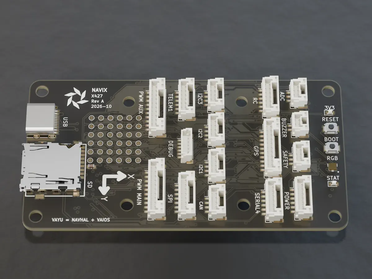
The same STM32F427 and the same stack, on a 36 x 36 mm board. It has one IMU instead of up to three, eight PWM outputs instead of fourteen, one I2C port instead of three, no SPI port, no microSD slot (16 MB onboard flash instead) and 6 test pads instead of 36.
Which software is it built for?
The in-house NavHAL, VaiOS and VAYU stack, on the same STM32F4 family and Cortex-M4 architecture as the X427 and the NAVIXSM-F401RE.
Does it have a compass?
Not on the board. Use the compass in your GPS module, which connects over the I2C2 bus on the GPS1 port.
How many motors can it drive?
Eight, on the PWM MAIN pads.
Does it log to a microSD card?
No. Logs go to a 16 MB flash chip on the board.
Can I use SBUS and CRSF receivers?
Yes. The RC port passes the signal through an XOR gate so inverted SBUS and non-inverted protocols share one port.
Join the Mini waitlist.
It is in design. Join the waitlist to be on the list, or write with your questions and an engineer will reply.